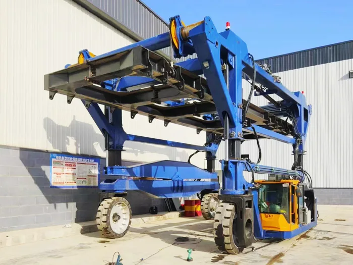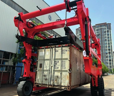
Plan a straddle-carrier site using the complete loaded envelope, swept path and wheel reactions. Overall dimensions, inner width and ground clearance are useful catalogue references, but they do not confirm door access, turning space, slab strength or trailer-loading capability for a particular project.
Separate the dimensions you are checking
On a small screen, swipe the table to compare all columns.
| Dimension | What it describes | Project use |
|---|---|---|
| Overall dimensions | Carrier length, width and height in the supplied table. | Initial access screening; confirm the offered configuration. |
| Inner width | Frame opening where explicitly listed. | Check the load and attachment with required working clearance. |
| Lifting-device dimensions | SSC35 lists a device width and height. | Do not substitute these for inner-frame width. |
| Secondary lifting height | A source parameter for the lifting arrangement. | Do not treat it as a stacking or trailer-height guarantee. |
| Minimum ground clearance | 200, 240 or 300 mm in the reviewed references. | Not a measure of ground strength, allowable slope or obstacle permission. |
Open the original Ruiding straddle carrier brochure (PDF page 3). The supplied manufacturer catalogue describes brochure versions; the current offered configuration is confirmed in a project proposal.
Draw one complete movement
Mark the pick-up position, loaded travel path, placement position and empty return route on a scaled layout. Include gates, doors, overhead structures, fences, parked equipment and temporary storage. Identify where the load changes height or orientation and where the carrier waits while another process completes.
Record the clear opening at each restriction rather than only the nominal building dimensions. Doors, beams, services and attachment projections can reduce usable space. A supplier’s loaded envelope should show the relevant travel and lifting conditions.
Review turns with a swept-path drawing
The overall length or width does not define a turning path. Ask for the proposed carrier’s swept envelope with the representative load and attachment. Check bends, reversing positions, entrances and any turn made near pedestrians, road traffic or other equipment.
The model comparison highlights a useful distinction: the 60 t and 80 t HKY references both list 3700 mm inner width, while the 80 t versions are wider overall. Use external dimensions for site screening and the internal drawing for load fit.
Give the ground review the correct load information
- Surface construction and available structural drawings or bearing information.
- Joints, trenches, covers, drains, ramps and transitions along the route.
- Gradient and crossfall measurements, plus uneven or damaged areas.
- Outdoor drainage, standing water and weather exposure.
- Supplier wheel reactions and the approved operating load cases.
A total carrier mass or payload figure cannot by itself confirm local floor or ground suitability. Obtain the proposed wheel reactions and have the relevant site structure assessed by a competent engineer. Catalogue ground-clearance values do not replace that assessment.
Include charging, maintenance and traffic areas
For electric AEV versions, mark the charging position and available electrical supply using the electric selection checklist. Identify access for maintenance and attachment inspection, and how those activities affect normal site traffic.
Describe pedestrian crossings, shared vehicle routes and operating restrictions. Ask the supplier to state visibility, signalling, control and protective-function arrangements for the proposed configuration. Agree how the site and equipment responsibilities will be divided.
Send a site-survey pack
| File or input | What to include |
|---|---|
| Layout | Scaled drawing with route, stations, doors and overhead restrictions. |
| Measurements | Clear openings, gradients, crossfall and transition details. |
| Load | Complete mass, centre of gravity, outline and lifting-point drawing. |
| Structure | Available ground or slab data, covers and crossing structures. |
| Workflow | Moves per shift, queueing, traffic and charging or maintenance windows. |
| Confirmation | Loaded swept path, wheel reactions and working envelope requested from supplier. |
Questions buyers ask
How wide must an aisle be?
There is no universal aisle width in the supplied data. Use the offered carrier’s loaded swept path and the site’s traffic and clearance requirements.
Does 300 mm ground clearance mean the machine can cross a 300 mm obstacle?
No. Clearance is not an obstacle-crossing approval. Review the route geometry and the supplier’s permitted operating conditions.
Can I confirm doorway access from brochure height alone?
Use the complete loaded configuration, attachment position and required clearance. A listed machine height is only an initial reference.
Request a route and access review
Send the marked layout, load drawing and measured restrictions through the project enquiry form. Identify which site questions need a supplier drawing or structural review.