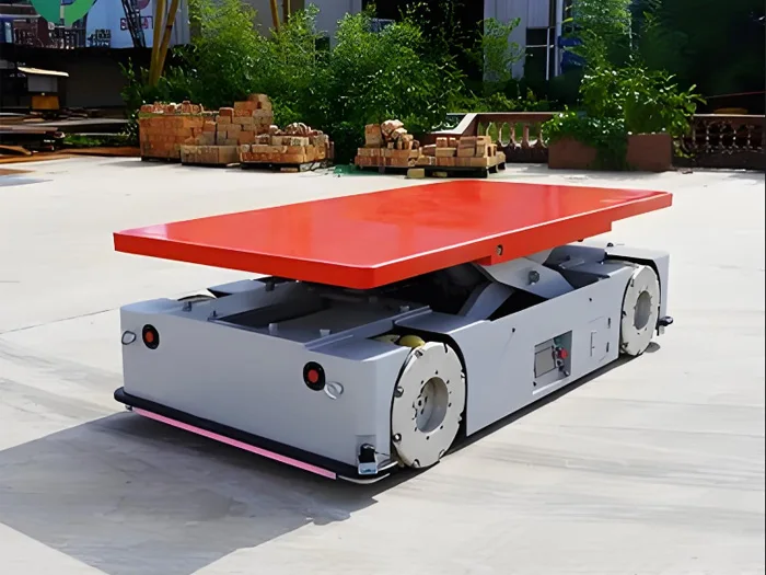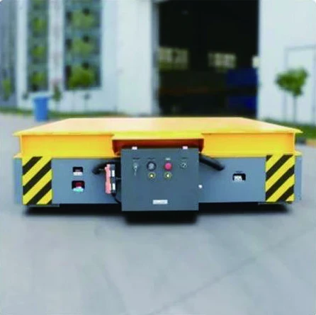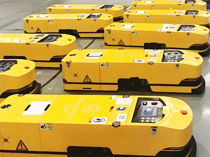
Ruiding’s AGV brochure describes three control layers: vehicle motors, drives and onboard PLC; wireless access points along the route; and an upper-level PLC for status processing and dispatch. A project brief should define the responsibilities, station handshakes and recovery behaviour between those layers.
The three control layers in the manufacturer source
On a small screen, swipe the table to compare all columns.
| Layer | Brochure description | Project definition needed |
|---|---|---|
| Vehicle control | Travel motor, drive and onboard PLC; sends and receives signals. | Vehicle states, local control, load state and fault information. |
| Network transmission | Wireless APs distributed along the route. | Coverage, handover, latency requirements and communication-loss behaviour. |
| Upper-level control | PLC processes vehicle status and higher-level instructions for dispatch. | Job assignment, route permissions, station readiness and supervisory interfaces. |
Open the original Ruiding AGV and transfer cart brochure (PDF page 4), printed page 05–06. The supplied manufacturer catalogue describes brochure versions; the current offered configuration is confirmed in a project proposal.
Separate the control diagram from the offered scope
The control-structure diagram includes dispatch, vehicle control, HMI, navigation, servo drives, sensors and safety or obstacle-avoidance blocks. It also labels an MES system. The following network-topology spread shows field HMIs, master DCS, WMS and a server labelled “MED”. Clarify the plant-system names and interfaces before specifying the project; the two diagrams should not be treated as a confirmed software package for every vehicle.
The component spread describes an industrial touch-screen HMI and integrated drive and steering components. The following spread includes a ground control cabinet, scanning radar and a wireless remote command station. These are manufacturer references for a scope discussion, rather than proof that a particular proposed vehicle includes every function. See PDF pages 5–6 for the topology and component descriptions.
Define an example transport sequence
- Request a move. Identify the sending system, job identifier, load information and destination.
- Check readiness. Confirm source station, destination, route permission and vehicle availability.
- Transfer and confirm. Define how the vehicle and station confirm load presence and transfer completion.
- Travel and report. Agree status messages, occupied-route behaviour and communication handling.
- Complete or recover. Confirm placement and job completion, or hold the cycle for an authorised recovery procedure.
This sequence is a requirements example. The agreed controls must match the selected navigation method, load-transfer mechanism and production process. Do not assume a specific protocol, controller brand or docking accuracy without a confirmed scope.
Make every station handshake explicit
| Signal or state | Question to resolve |
|---|---|
| Ready to receive | Which system confirms the station is clear and available? |
| Load present | How is load presence and correct positioning detected? |
| Transfer permitted | Which conditions must be satisfied before movement or lifting? |
| Transfer complete | Which system confirms success and releases the next step? |
| Fault or timeout | What remains stopped, who is notified and who can reset? |
| Manual operation | Which commands are permitted and how automatic control resumes? |
Review wireless and fault recovery together
Use the AGV site-survey guide to map route coverage and shared operating areas. Ask for the specified behaviour when communication is interrupted, a destination is unavailable or the vehicle stops with a load. Assign reset authority and define how the job state is reconciled before restarting.
Network supervision and production handshakes do not by themselves validate protective functions. Review scanning zones, stopping behaviour, emergency-stop scope and restart conditions for the selected vehicle and site. Agree the required risk assessment and validation with the responsible parties.
Ask for a controls deliverables list
- Architecture showing vehicle, route network, supervisory controls and plant interfaces.
- Signal list, data ownership, protocol and change-control responsibilities.
- State and fault definitions, including communication loss and interrupted transfers.
- Operator roles, HMI functions and manual or maintenance modes.
- Acceptance scenarios covering normal cycles and agreed abnormal conditions.
Questions buyers ask
Can the AGV connect to our WMS or MES?
The brochure diagrams reference plant systems, but project compatibility is not established. Provide your interface documentation and ask for a confirmed integration scope.
Is dispatch the same as onboard vehicle control?
They have different responsibilities in the brochure: onboard controls operate the vehicle, while the upper-level system processes status and dispatch instructions.
Does the scanning-radar description prove site safety?
No. The proposed sensors, protective functions, stopping conditions and operating environment require project-specific assessment and validation.
Prepare an AGV controls enquiry
Share the station sequence, plant-system interfaces, route layout and required recovery cases alongside the AGV project checklist. Request a control-scope review.